Welcome to my site! It houses the longest KX100
Plus telephone box that I've seen on the internet. Unfortunately you can't make calls ✆ or texts ✉, but
you can send mail @ if you'd like to comment on a post! Please ask if you'd
like to have your thoughts featured at the end of an article.
You will find my most recent posts below which often include
project diaries and interesting links from across the web.
I've been using Token2 PIN+ security keys for a little over a year and a half now. They're a FIDO2 certified key that can hold Passkeys and generate OTP codes, often cited as a cheaper alternative to their main competition: Yubikeys. Unfortunately, I've had very poor luck with their durability.
If you want the short version of this review, I suggest you suck up the higher price and go for a Yubikey instead. Although Token2 keys function great, the durability of the PIN+ Type C series just isn't good enough and it can't stand life on a key chain.
The First Victim
The main reason for getting one of these keys was so that my one time passcodes and security keys were contained in a physical and distinct device. The whole purpose of OTPs is to prove that you know something and they often comprise the possession factor (something you have) of a security measure. The physical analogue of this are keys you keep on your keyring, so for me it makes most sense to put my digital keys there too. However, this is the location where my first Token2 security key fell victim.
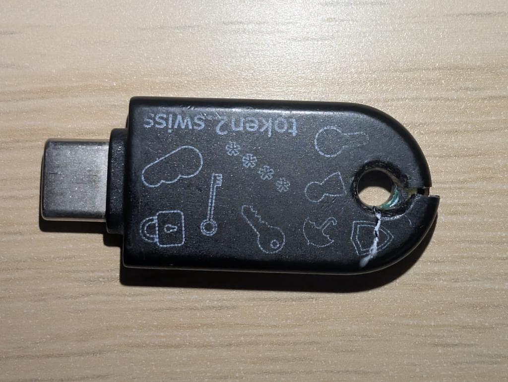
The first key I bought from Token2 was a PIN+ Release 2 but I only had it on my keyring for 4 months before the hole on the top cracked, presumably from pressure against my keyring.
Fearing that further damage might occur to the electronics inside I bought a second one and transferred my secrets to it.
The Second Victim
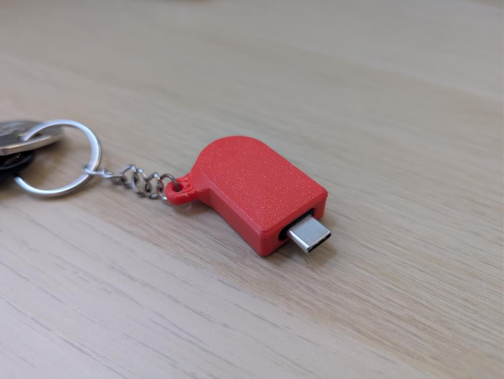
That leads us to today where, once again, I've got a broken Token2 security key. For the second key I brought a PIN+ Release 3 which is almost identical the first one apart from the bigger number in the name. I thought I'd take greater care over this next key so I 3D printed a case so that I didn't have to directly attach the key to my keyring. That way, hopefully I'd avoid the immense crushing power of my pocket breaking the plastic casing again.
The 3D print included a pause so that I could insert the key into the case before the printer permanently cinched the key into it's new plastic home. The fit is very good so do give me a shout if you already have a Token2 key you'd like to protect and would like the files.
Although this new key didn't get crushed, after a year the USB-C port stopped working which made it useless for devices without NFC. A real shame because both of these keys worked so well when they were new. This leaves me only able to recommend the PIN+ Type C series if you're the sort of person who likes to keep their keys in an anti-static bag, away from hench pockets. Hopefully, their other mechanical designs are more robust but I've been stung twice too many and I won't be made a fool for a third time.
The Solution?
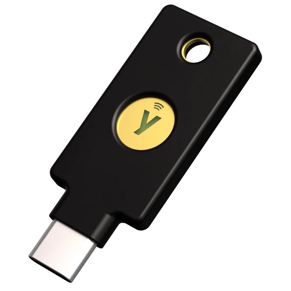
So what's going to be replacing my malfunctioning key? After two failed attempts, I've decided to take the "buy once, cry once" approach and get an expensive Yubikey after all. More specifically a YubiKey 5C NFC.
It's still especially important to save those bytes as the globe doubles down on mobile browsing. These reports are great for seeing what device and network conditions you should optimise for.
(Fixed the link for "Signing Git commits and tags with SSH")
Cloudflare Outage Memes & Commentary
Lucky for me nothing I depended on went down the other day, not even this website! However, it is worrying how a large proportion of a distributed system like "The Internet" can be brought down by a single company.
I like to look at this one through the lens of re-evaluating all tools that you're currently using and seeing if they're really worth the headache they cause along the way.
Living in a flat in the middle of a city has its perks but having neighbours within throwing distance of all your windows is not one of them. For better or worse, opening and closing blinds is an essential part of my day but one which can be automated!
The goals of this project are as follows:
Integrate with my existing Home Assistant instance for easy remote control and scheduling.
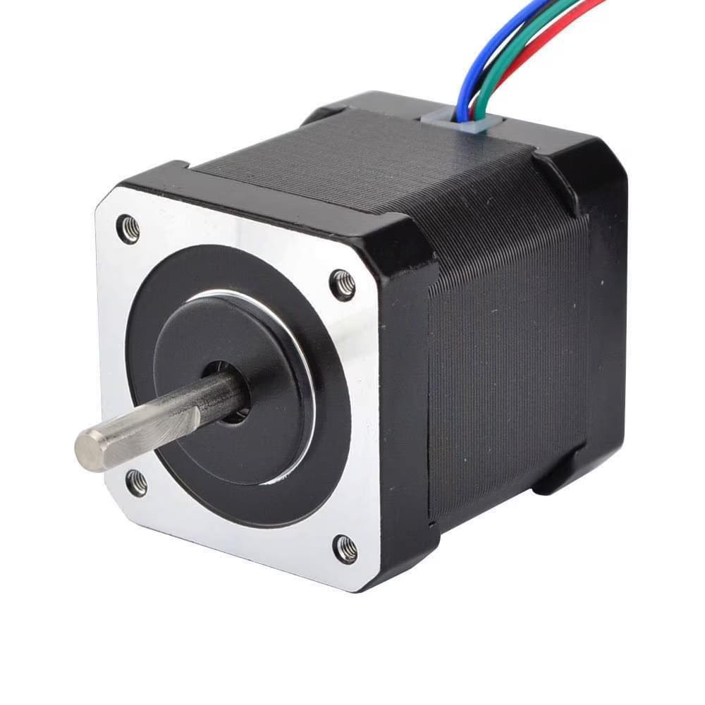
Make use of the stepper motor drivers that have been sitting in my parts drawer for too long.
Have as many parts 3D printable as possible.
The Mock-up
Electronics
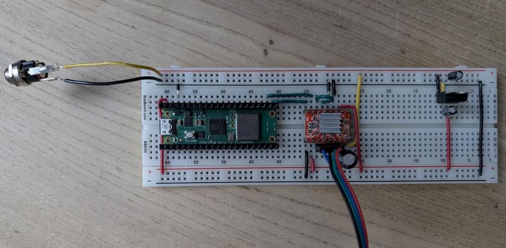
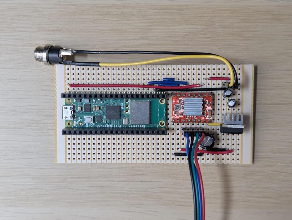
To get things started I laid out some components on a breadboard so I could get the stepper motor moving. The brains of the project is a Raspberry Pi Pico W running ESPHome. This is connected up to a cheap A4988 stepper motor driver powered by a 24v supply.
To step down the 24v to 5v, for the Pico, I used a simple L78 linear regulator. This method of stepping down voltage is terribly inefficient as the difference between the supply and output voltage is bled off as heat.
This means that given a peak power draw of maybe 100mA for the Pico and A4988 combined, the little regulator would be dissipating 1.9 Watts. The regulator has protections to ensure that is doesn't overheat but it would definitely require a heat sink for the final build.
Software
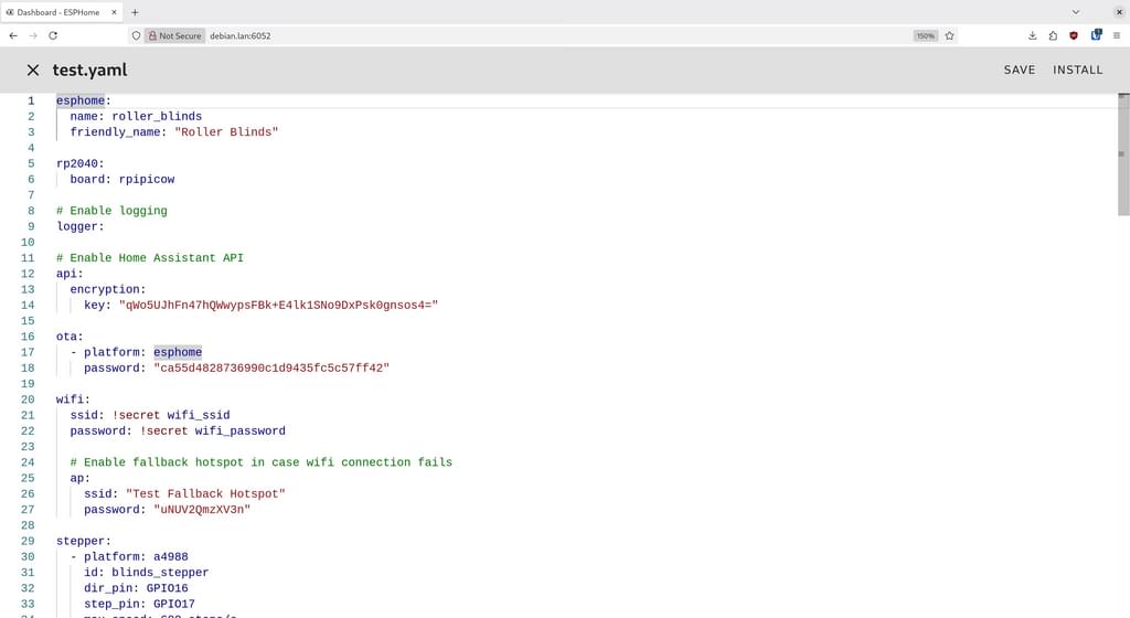
Next is configuration to enable ESPHome and Home Assistant to interact with the motor. ESPHome provides a Docker container that can generate firmware for your microcontroller based on yaml files for configuration. After some hacking I had something like this:
The stepper component makes it super easy to use stepper motors with ESPHome by only defining a couple of GPIO pins. However, Home Assistant can't directly control stepper motors so we need to expose it as a cover:
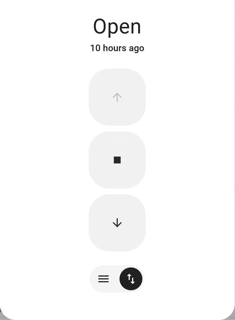
Here I'm using a template to expose a function that Home Assistant can run on the microcontroller. More specifically I'm using the cover template. This allows Home Assistant to show a nice interface to allow precise control of the blind, including buttons to open, close and stop the thing too.
Gearing
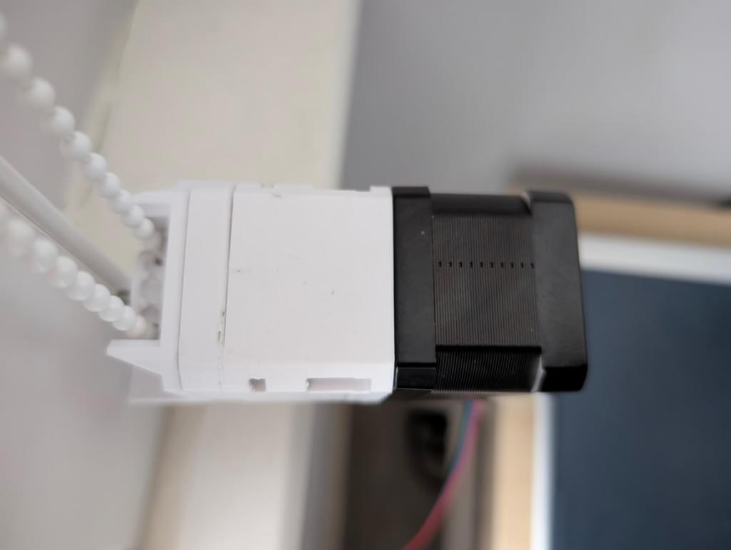
My blinds are huge and heavy, even with the maximum current the A4988 can provide they won't budge under just the power of the stepper motor. To get an output with enough torque to move them I'm using this 5:1 planetary gearbox that a co-worker recommended when he got earshot of my issues.
It wasn't a long print and after assembling using the parts list in the description, the operation is smooth and quiet. With the new gearbox mounted the blinds are moving just fine and it's not such a strong reduction that it can't be back driven.
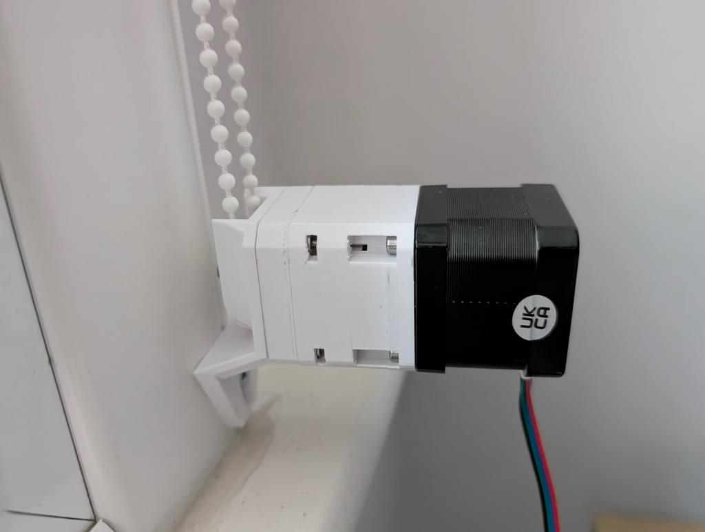
The Installation
To attach the assembly to the wall I remixed this mount designed to motorise bead blinds to fit where the plastic loop holding the blind beads was screwed to the wall. However, once again my very heavy blinds strike back! The beads don't have enough grip against the gear from the model, so I further modified the design to fit a gear that completely surrounds each bead to grip it. With that the mechanical interface to the blinds is complete, but a breadboard isn't permanent enough for something I want to leave plugged in 24hrs a day.
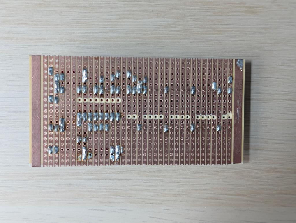
This is the schematic for the final circuit which I built up onto some strip board I had lying around:
I did contemplate having a PCB made up, but for a one-off prototype I prefer the convenience of having it made in an evening. It certainly brought back some school memories of using a drill bit to break the strips.
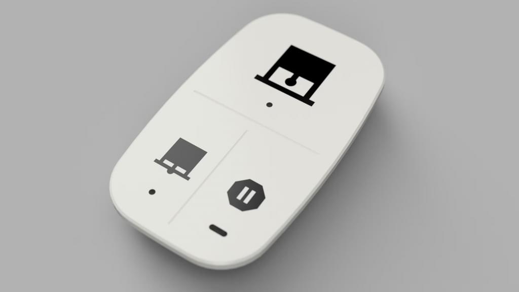
I measured up the board and designed a small box that can hide everything out the way. It's all well and good being able to automate your blinds or control them through your phone but that isn't so intuitive if we have people round. To that end I configured a SOMRIG Zigbee button and printed off a custom face place to give some hints for what it is for. A few people have made some excellent resources and I used an existing faceplate model in combination with Aasikki's button template to create a reasonable design using Autodesk Fusion.
With that I'm rather pleased with how the whole installation came out. The only remaining issue is that the whole system operates by dead-reckoning. Occasionally the stepper motor slips or there's some delay in ESPHome which causes the position of the blind's open and closed states to drift out of sync with reality. I've made a number input, in Home Assistant, that allows me to trim the blinds back into position if it becomes an issue but after several months I haven't had to use it often enough to be a problem. The only real problem now is that I've got a project shaped hole in my evenings that will inevitably be filled with Clarkson's Farm and Taskmaster. I'll just have to wait until another idea crosses my mind.
Models & Configuration
You can access the configuration required to make this project work on my GitHub. I haven't posted the 3D models yet but if you want them before they're up, give me a nudge on blinds@bweston.uk.